Mercury Panel Initialization - https://www.qumulex.com/kb/qxep
If the Controller board is stuck in this state, the LP1501/02 is having connectivity issues. Follow these steps to remedy.
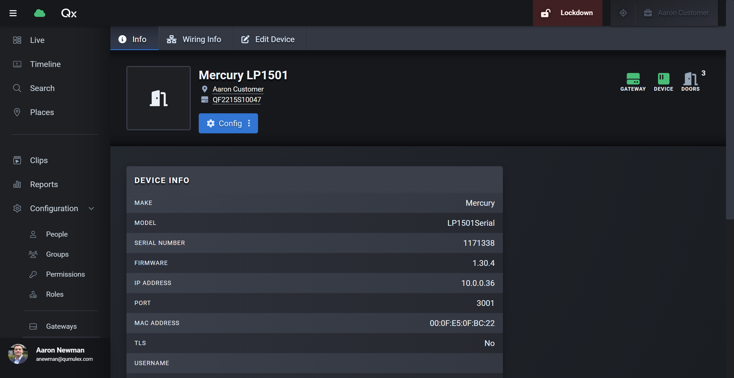
- Ping the IP on configured for the board, perform this from a PC on the same network as the device. If no reply, then confirm the device has been programmed to match the Gateways IP scheme, a quick way to check is match the PC to the default subnet of 192.168.1.x and try to ping 192.168.1.251. If it replies back on that IP then the device is still on the factory IP.
- If the board pings on the programmed IP matched to the gateway's IP Schema for the LAN or WAN port, but is showing offline still.. Check to make sure Places have been set for the 'To' and 'From' of the door config. Check that a Group exists for the door that are part of that controller. Check to make sure Permissions exist for the doors that are part of the controller. Without a complete configuration, the board will appear offline, until this piece is successfully pushed to controller.
- In some rare cases a full memory wipe has proved to bring problematic boards back on line and acceptance of the field tech defined IP. Or in cases where the web page is responding very slowly or not at all, even trying different browsers. Follow the Bulk Erase Steps Below.
Bulk Erase Configuration Memory
If the LED's do not initially follow this sequence, i.e. LED 1 pulsing steadily but nothing else.. power off for 30 seconds and attempt again.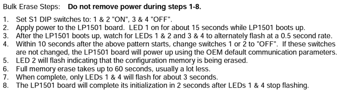
MR52 Troubleshooting (LP1501 Serial and LP1502, LP2500, LP4502 SIO connections / Mercury Inventory)
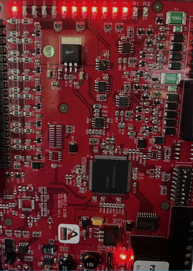
The picture above shows a successful board connection with the Gateway.
With your respective Controller board in this state, you know the Controller is talking but the is a break in communication between the Controller and down stream SIO modules. One of the issues will be the link light on LED 'B' Will be off. (See Picture Below) This indicates no communication back to the controller as pictured below. Some possible causes could be:
- Dipswitches
- SIO Wiring / Termination
- Power
The SIO 485 Bus will start at the controller and daisy chain to each MR52 in the door kit, with the last one being terminated. From my own internal testing the last board does not require termination if all boards are in the same enclosure. Only in cases where the boards are spaced out across a building and several hundred feet of SIO 485 cable exists, termination of the final SIO module would need to take place.
To terminate the End Of Line, on the last SIO module ie. MR-52, install the jumper across both PINs on J4.
Starting with DIP Switches, some example address would be
MR52 - Address 1 - SW1 ON, SW2 OFF, SW3 OFF, SW4 OFF, SW5 OFF
MR52 - Address 2 - SW1 OFF, SW2 ON, SW3 OFF, SW4 OFF, SW5 OFF
MR52 - Address 3 - SW1 ON, SW2 ON, SW3 OFF, SW4 OFF, SW5 OFF
MR52 - Address 4 - SW1 OFF, SW2 OFF, SW3 ON, SW4 OFF, SW5 OFF
MR52 - Address 5 - SW1 ON, SW2 OFF, SW3 ON, SW4 OFF, SW5 OFF
Ensure the boards have been properly addressed is step one, step two is check that all MR52's have SW6 ON, SW7 ON, SW8 ON. 6,7,8 set baud rate.
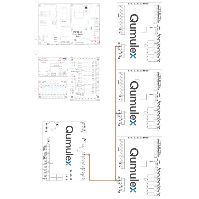
Above is an example of SIO Wiring from the LP1502 (Bottom Left) to each of the MR-52's. MR-52's are easily identifiable as having the bank of LED's at the top of the board.
After checking that each board's dipswitches are set with correct address and baud rate and still have no 'B' LED activity, proceed to check the SIO wiring.
This three wire connection should have a TR+, TR-, and GND. Each TR+ must be landed and daisy chained to the other MR52's TR+'s. If a TR+ on one board is accidently landed in a TR-, or GND it will kill the SIO communication. Its recommended to use separate colors for each termination for example all TR+ is RED, TR- is BLACK, GND is the unshielded silver ground in the case of shielded 22/2 or another color if using a different cable.
If all the above checks out check voltage to the boards. If using a 12v source where the readers are configured for pass through power, its recommended that the power supply be capable of supporting up to 300Ma per connected reader. If using our LSP kit the power supplies spec'd are sized appropriately, this could potentially be an issue if using third party door kit hardware / power supplies.
The input voltage on the MR-52 should be 10.8-13.2 vDC
If using a 24 volt configuration the input voltage should be 22.8-25.2 vDC, and ensure the reader jumper next to the relays on the bottom right side of the board is set for 12v and NOT PT (Pass Through) or reader damage will occur.
With OSDP reader deployments our standard when landing multiple readers to a reader port. Reader 1 must start with address 0 and the standard baud rate is 9600.
Alternatively if landing one reader per port, the schema would still be the same the reader is addressed as Address 0, and Baud rate 9600.