To initialize your QXEP-LP panel within the Qx Control software, it will require a IP address that in is sync with your Qx Gateway's IP scheme preferably on the LAN segment. The next few steps will walk you through accessing the web page and getting the LP Controller on your Gateway's IP schema.
(Step 1)
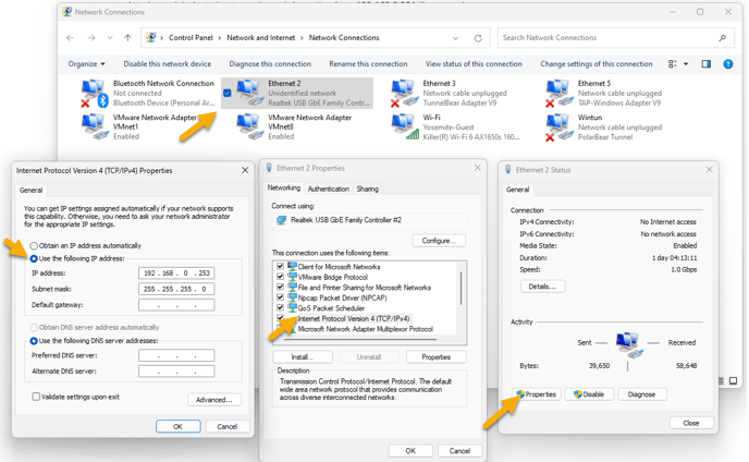
Set your PC to match the same IP Schema as the QX Controller. To do this navigate to Control Panel > Network and Internet > Network Connections.
Select the interface that is connected to the Controller's Network.
Select Properties on the Ethernet interface.
Double Click on the Internet Protocol Version 4 (TCP/IPv4) Line item.
Use an IP address such as 192.168.0.253 with a subnet mask of 255.255.255.0
Click Ok
(Step 2)
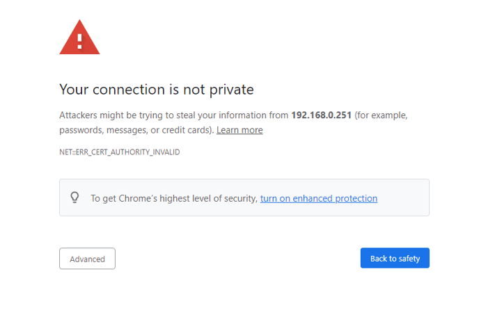
Open a web browser from a Laptop or Computer connected to the same network as the QXEP Controller. Navigate to the default IP address of 192.168.0.251
Click Advanced in the bottom Left Corner and Click, Proceed to 192.168.0.251(unsafe)
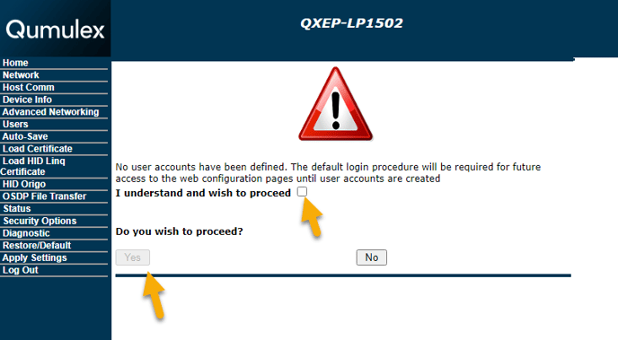
(Step 3)
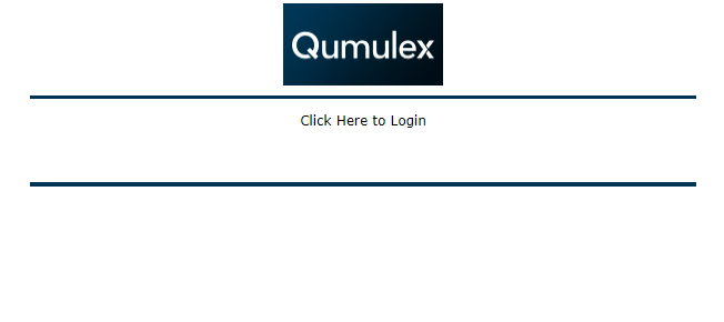
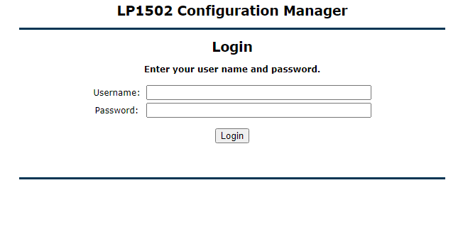
After you click "Click Here to Login", you will be presented with a Login screen. To enable the default credentials. User name: admin , Password: password flip the onboard dipswitch 1 to ON.
Login using the default user name and password.
If you plan on administering or updating the Controller via Go to Webpage in the future, now is a good time to set a user name and password to access the controller without having to flip dip switch one physically in the future.
Navigate to the Users tab and create a user and password.
(Step 4)
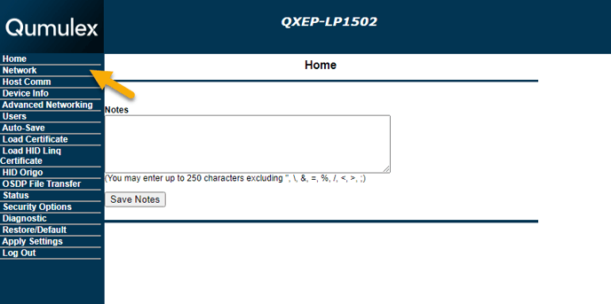
After Login, Click on Network
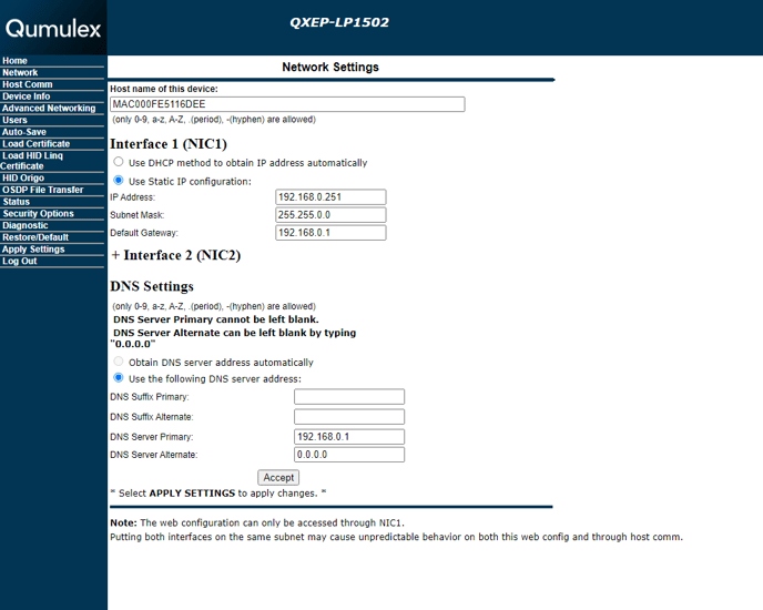
Click on the toggles to 'Use Static IP Configuration:' and set the IP address to match the Gateway IP Schema.
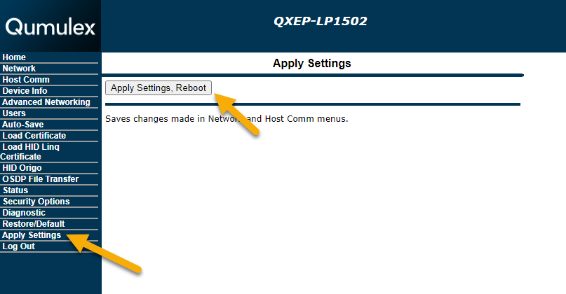
Click Apply Settings from the Left Side menu.
Click 'Apply Settings, Reboot' - At this point you will need to flip Dip Switch 1 on the LP Controller back to OFF
Adding MR52-S3B / MR50 Reader Interface Boards to QXEP Controllers:
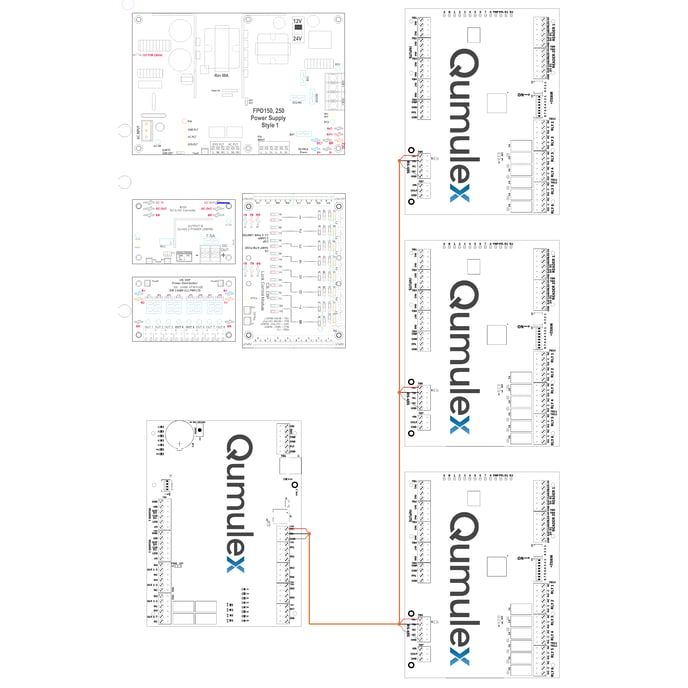
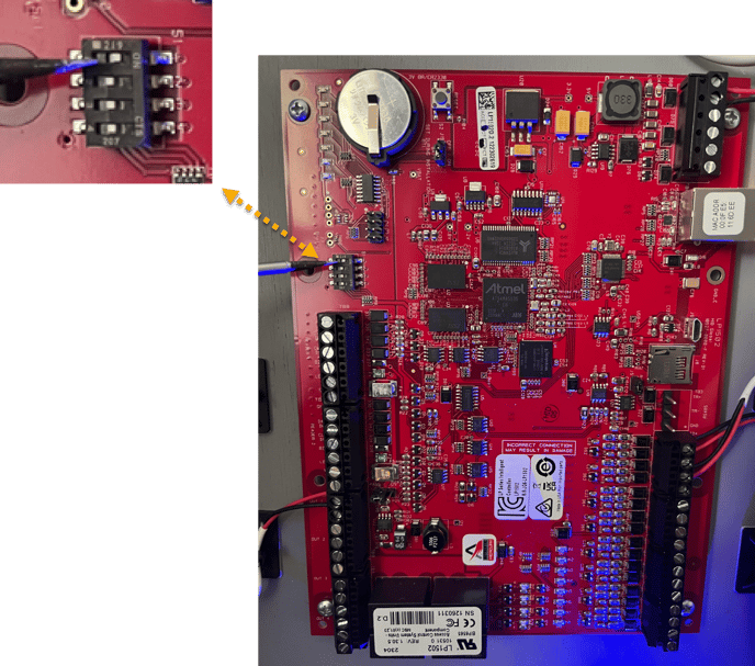
This guide assumes the boards are powered up, and RS-485 Daisy chain is starting from the controller to each MR board in the enclosure.
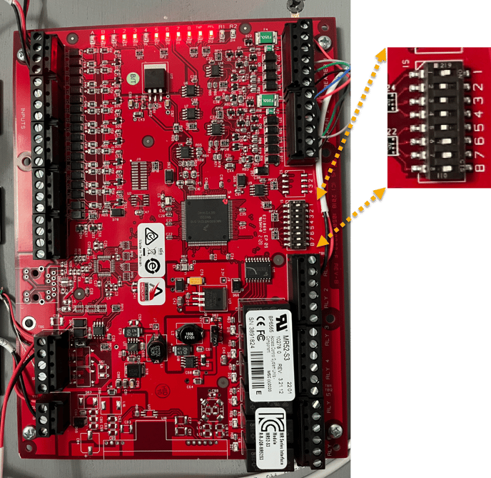
To establish communication with MR-XX boards, each board must be uniquely addressed starting with address 1, and the baud rate set.
In the example above, for address 1, dip switch 1 is set to ON
Dipswitch 6, 7, 8 are set to ON for 38,400 BPS and Encrypted Communication.
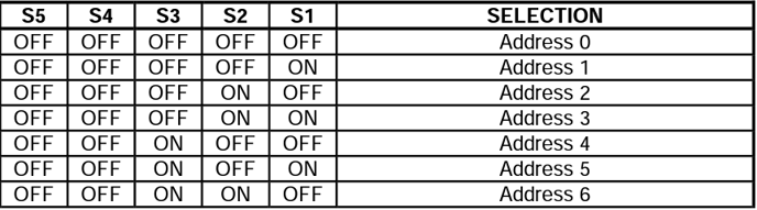
The Chart above references address 1 through 6. Each board on the (SIO) RS-485 daisy chain will need a unique address, as well as Dipswitch 6,7,8 set to ON.
The Hardware configuration is complete, now the software can be programmed within Qx Control to program the controllers and doors.
if you are experiencing issues after the software configuration has taken place please see the following guide LP1501/02 Connection Troubleshooting https://www.qumulex.com/kb/lp1501/02-serial-attached-mr52-troubleshooting