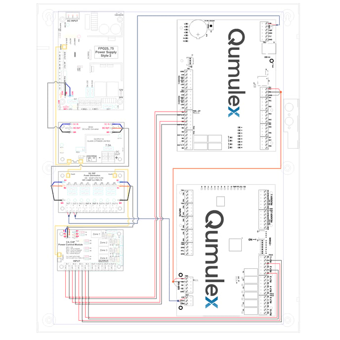
The above panel drawing is High Resolution, for more detail, you can zoom in with CTRL+Mousewheel to view terminations and board markings.
Overview of Wiring:
In this diagram the FlexIO (Yellow Cable) daisy chains between all the component boards to provide fault and Fire Alarm Interface through the system.
System power is provided by the three wire buss connectors provided with the Door Kit. The blue, orange, black wire harness can be connected using the soldered spade connectors on the modules shown in the drawing. Blue is 24v, Orange is 12v from the B100, and Black is the ground.
Output 1 on the D8 to TB4 on the QXEP-LP1502 provides Class 2 12v power as required by Mercury.
Components:
FPO75 - Provides 24v @ 3A. The output is selectable between 12/24V by the two position jumper in the center of the unit. The FPO 75 will charge 4 to 40 Ah of battery capacity.
B100 - is responsible for stepping down the 24v from the FPO75 to provide 12v system power. Input power for the B100 is derived from the FPO75 which is set for 24v.
D8 - Provides 8 protected DC outputs for use by the QXEP system. each individual voltage output zone may be programmed for a continuous output or to respond to a fire alarm interface for control of egress locks at one of the two system voltages.
C4 - The C4 lock controller module provides 4 access control inputs capable of voltage or dry contact activation. Each lock output is programmable to either 12v or 24v DC.
QXEP-LP1502 - Qumulex Access Controller powered by Mercury. Supports 2 Doors Directly attached, with 4 readers, 8 inputs, 4 outputs.
Component Settings:
B100 - The JP3 on the B100 should be set to Position 1 from the factory, and what Qumulex recommends. Setting the jumper JP3 to position 2 allows an adjustable output range from 5 to 18Vdc using the VR1 on board potentiometer.
D8 - Has selectable jumpers on each output labeled JP1 through JP8 and are used to select the output voltage for each output in dual voltage systems such as this kit. Position 1 selects 24v, Position 2 selects 12v.
D8 Output 1 needs to be set for Position 2 for the QXEP-LP1502 prior to power up.
Its best practice to meter check the voltage output from the D8 output prior to installing the TB4 connector on the QXEP-LP1502 to ensure all upstream devices have been wired properly.
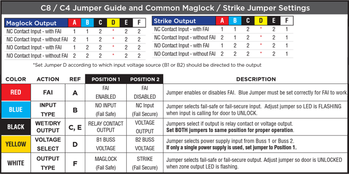
C4 - Please see chart below for C4 dip switch configuration.