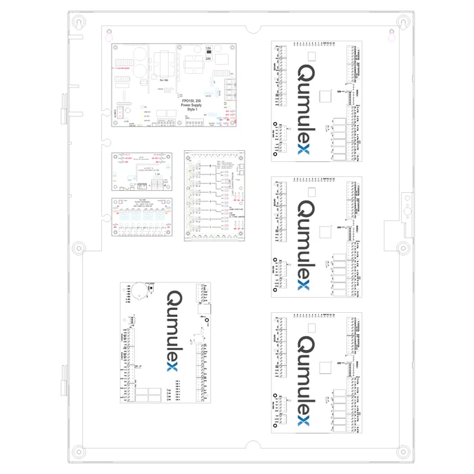
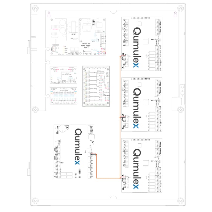
Pictured above is one interpretation of how to position Life Safety Power Modules and Qumulex Access Panels. The Mercury backplane allows for a number of configurations to assist in position of field wiring and orientation of panel knockouts as it relates to terminating the wire to the modules.
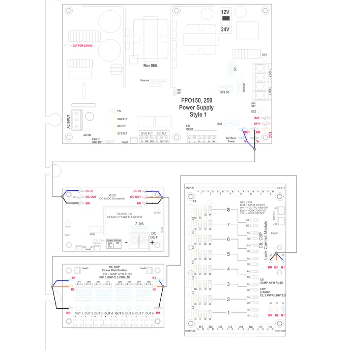
The included Black, Blue, Orange power buss is installed on the male spade connectors as shown.
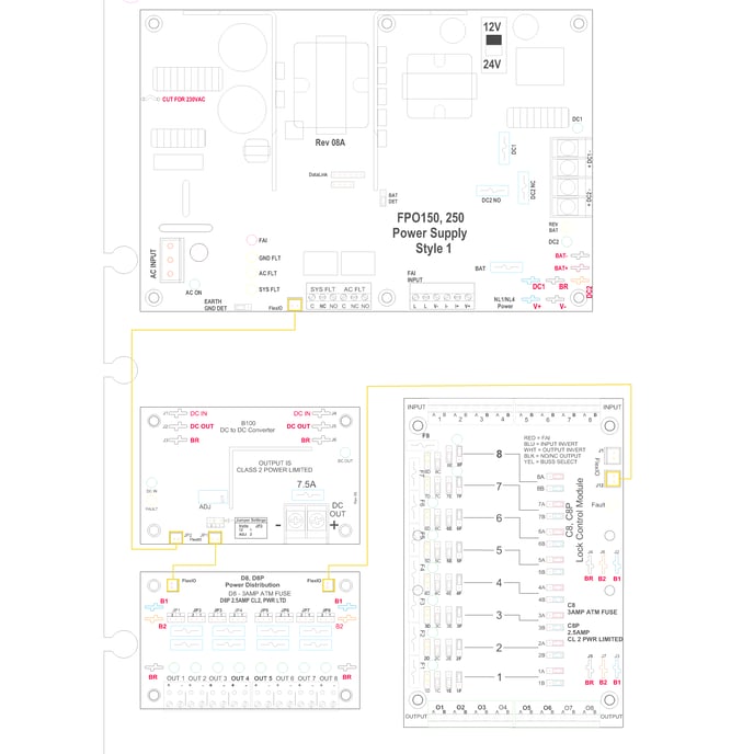
The Flex IO connector which is typically an included white cable with Keyed end is installed as shown.
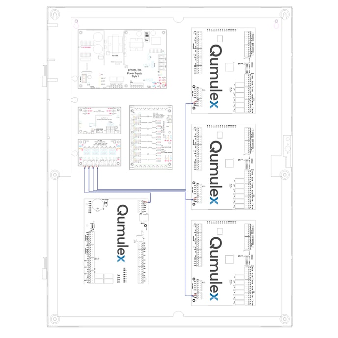
The wiring above shows the power cabling from the corresponding fused output on the D8 to the Qumulex Controllers.
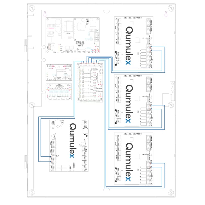
The orange cabling above represents the daisy chained 485 SIO buss from TB3 on the QXEP-LP1502 to the down stream MR52 modules.
From the QXEP-LP1502 & QXEP-MR52 outputs run a pair of wires to the inputs on the C8/M8 Module. When the output is closed on the controller side it signals to the C8/M8 to fire the lock output. The field wiring form the lock will land on the Output Terminal block on the C8/M8.
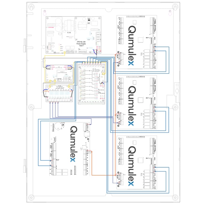
The above picture shows the completed cabinet. Some considerations to be made is where the nipple from a cable tray, or knock out for conduit / field wiring will be made on the enclosure.